Aeternum.ENGINEERING
Case studies / Modular ladder frame

Modular aluminium ladder frame for electric van and light-truck bodies

One frame family, several bodies and wheelbases, every metal part cut from stock. Chassis architecture, suspension packaging, FEA and a fabricator-ready pack for a US manufacturer's EV platform.

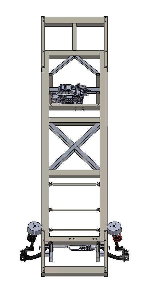
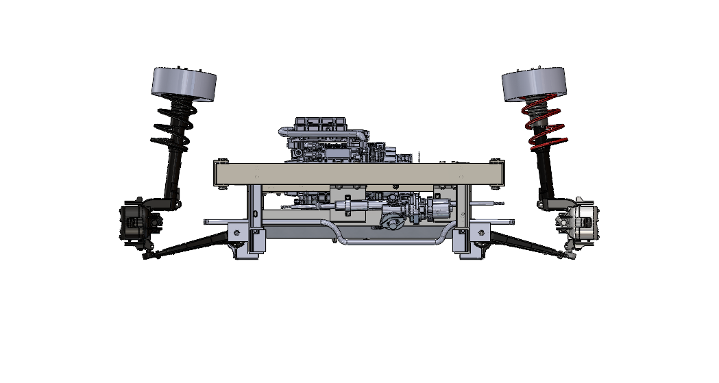
Front view of the ladder frame with laser-scanned donor struts, lower arms, steering rack and anti-roll bar packaged between the rails
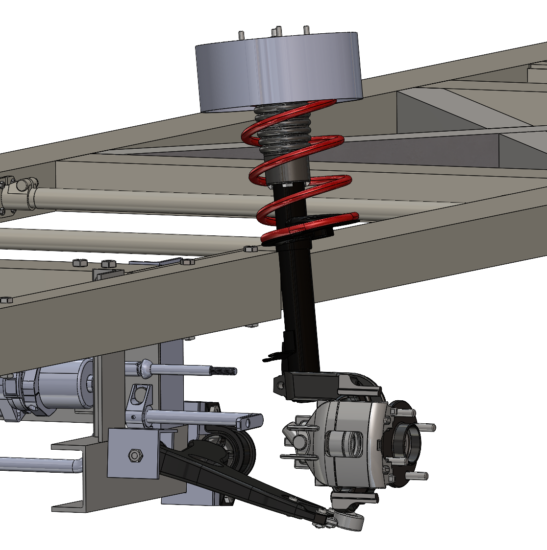
Front moduleLaser-scanned donor struts and lower arms on bolted mounts, steering rack and anti-roll bar packaged between the rails.

The brief

The client needed one frame that could carry several van and light-truck bodies, at more than one wheelbase, on donor suspensions they could source locally. It had to be buildable by a general fabrication shop without CNC work, hit defined stiffness targets, and arrive as a complete pack the shop could cut, weld and bolt from without further engineering input.

What I designed

A flat, bend-free ladder frame in which every metal part is off-the-shelf 6061-T6 stock: 5 x 3 x 1/4 in rectangular-tube main rails, channel and angle crossmembers, and three 1.25 in round torsion tubes on bolted lugs. Members are welded where the load path demands it and bolted where the client wanted modularity, so the front module, rear module and pack bay can move along the rails for a different wheelbase or body.

The front suspension was laser-scanned from a 2005 light commercial van, rebuilt in CAD and packaged with its steering rack and anti-roll bar on bolted mounts. A rear-mounted Cascadia IDM190 drive unit sits on stock angle and plate brackets, with a central bay reserved for the battery pack.

Validation in three iterations

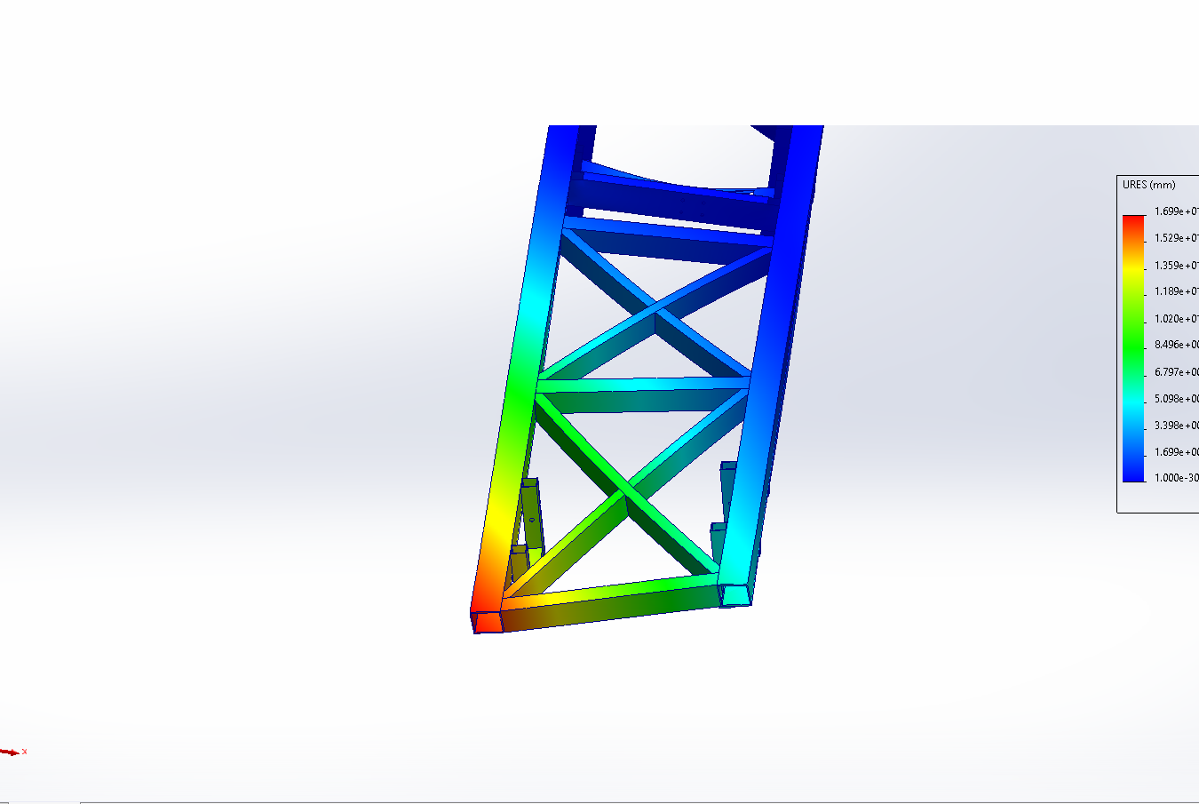
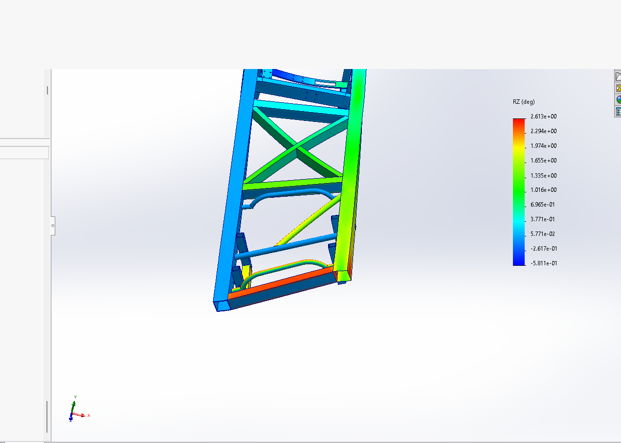
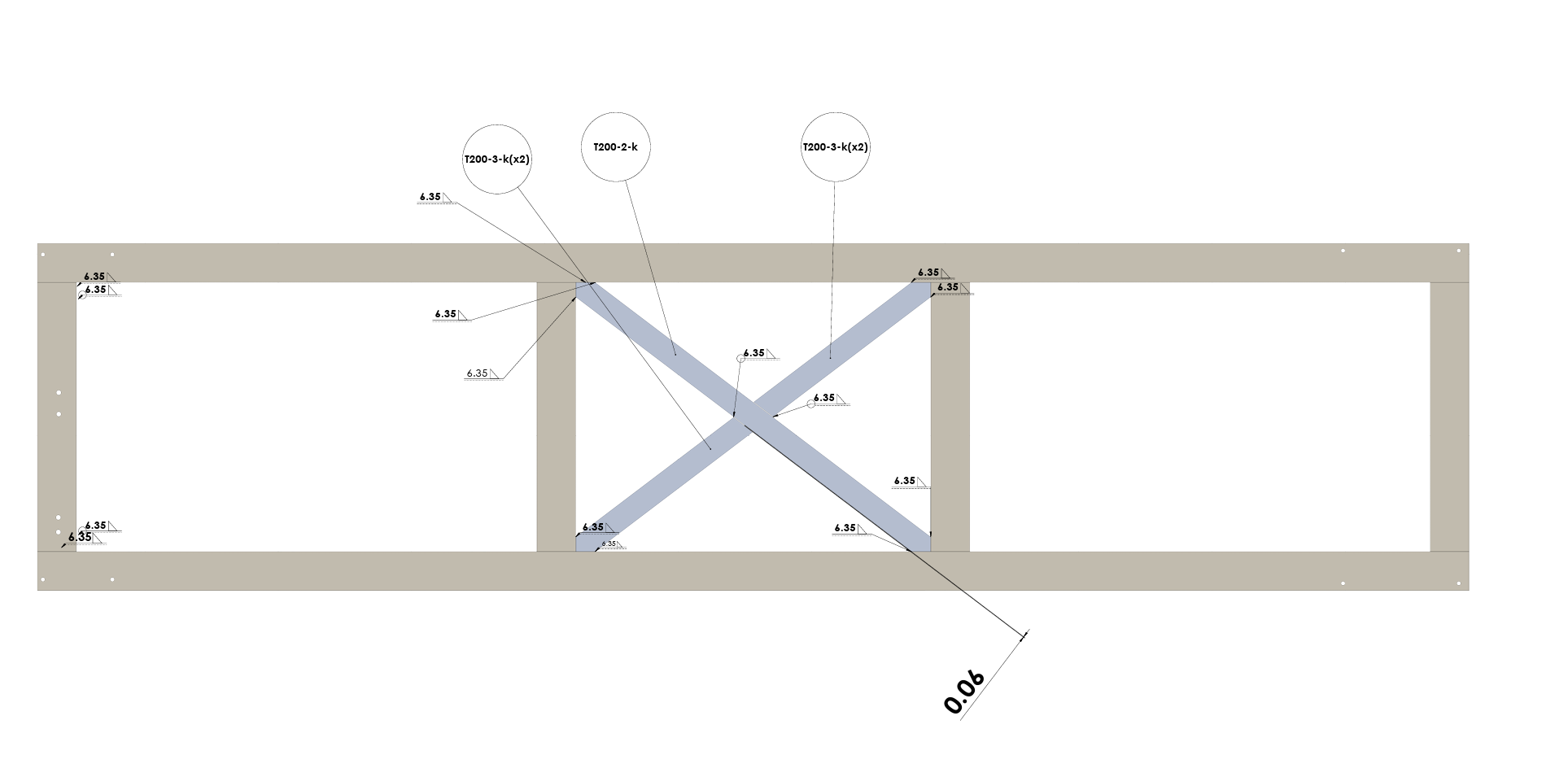
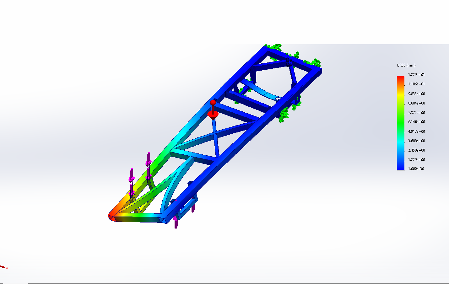
Targets were 4 kNm/deg in torsion and 3 kN/mm in bending. Weld connections were defined member by member in SolidWorks Simulation and the front section was reworked until the frame passed. A bent-tube front was also trialled and gave no meaningful gain over straight members, so the production frame keeps straight stock.

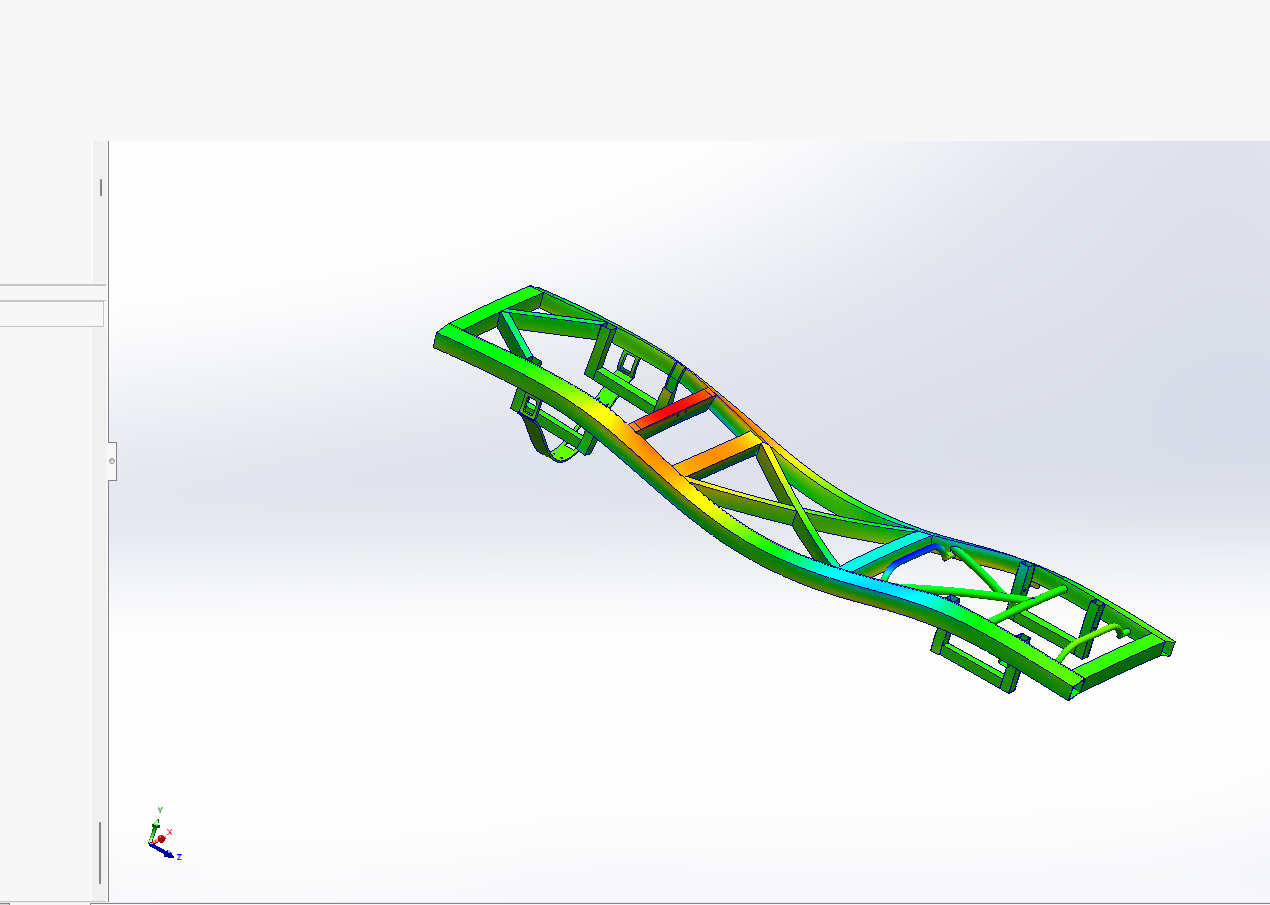
  1. Torsion displacement plot of iteration 1 with A-shaped front brace
    Iteration 1. A-braced front. Under half of the torsional target.
  2. Torsion displacement plot of iteration 2 with X-brace at the front
    Iteration 2. X-brace at the front. Better, still short.
  3. Torsion displacement plot of iteration 3, the final frame
    Iteration 3. Front section revised. 4200 Nm/deg, 105% of target.
Torsional stiffness4200 Nm/deg
Bending stiffness10 kN/mm
Safety factor4.5
Material6061-T6, 100% stock
Wheelbase3900 mm
Front track1827 mm
Frame mass, bare / complete126 / 150 kg
Forming or CNCNone

Delivered

Full CAD and STEP release, cut list and cut drawings for every section, a 30-page assembly pack with weld sheets, fastener stacks and tightening torques, and a bill of materials keyed to McMaster-Carr and MetalsDepot part numbers so the shop could order directly. Build is in progress with the client's fabricator.
Have a chassis or subsystem that needs the same treatment?

Vehicle dynamics, suspension, chassis and packaging, with FEA and design for manufacture. I do the CAD, analysis and documentation myself, remotely, and can own a full vehicle program or one defined piece of it.

Send me the brief Download the full case study (PDF)